Thermal-hydraulics deals with the investigation of heat and flow dynamics in nuclear reactors and their associated systems. The thermal-hydraulics group at NTI is involved in the safety analysis of nuclear reactors and nuclear power plants, in computational simulations of operational and accident processes. Intensive research is being carried out in Computational Fluid Dynamics (CFD) applied for nuclear energy analyses. We use the available measurement and experimental background to review and validate the applied numerical methods. In cooperation with the reactor physicists of the Institute, the development of educational nuclear power plant simulation program is also in progress.
Application of CFD in nuclear energy research
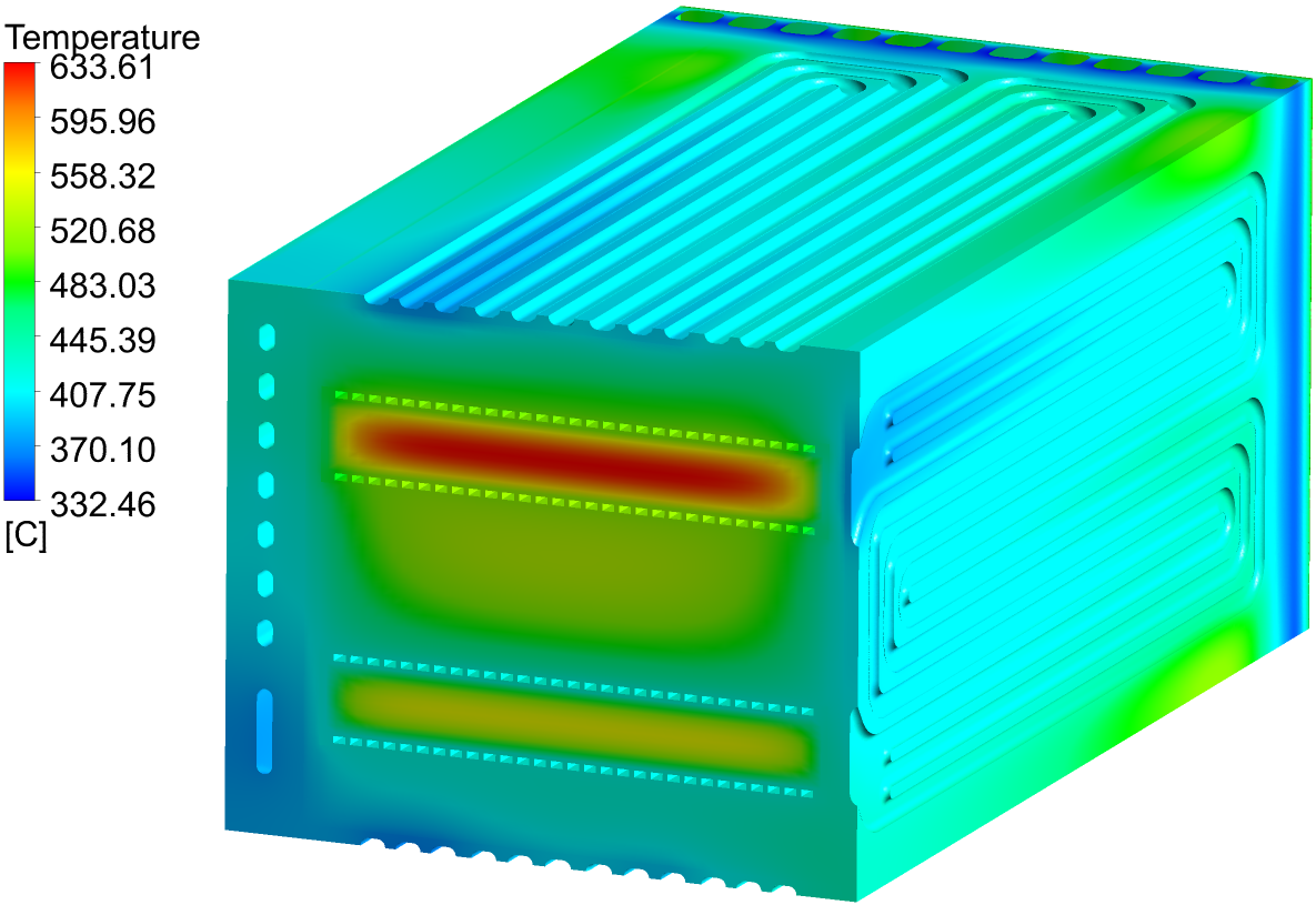
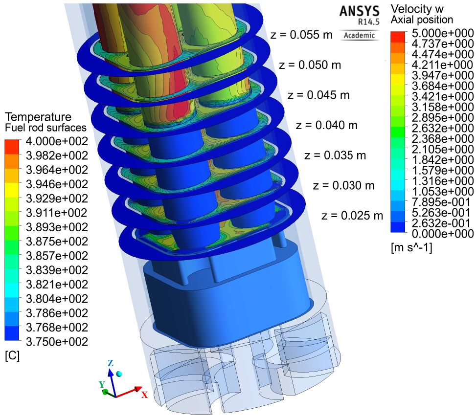
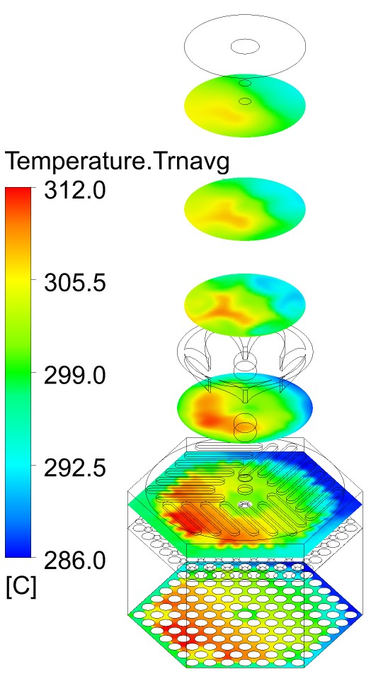
The discipline of CFD deals with the numerical calculation of flow and associated phenomena (e.g. heat transport). The method can be used to describe three-dimensional thermal-hydraulics processes in fuel assemblies, reactor pressure vessels, different pipelines and components of fusion reactors.
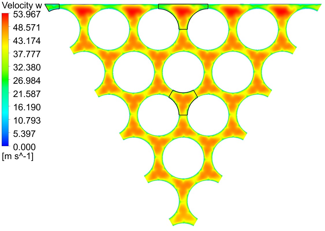
With this method we can get a detailed view of the coolant flow, pressure and temperature distribution of the investigated systems or components. Based on the results, we can understand the different thermal-hydraulics processes in detail, and the simulations help the safe design and operation of nuclear systems.
NTI uses ANSYS CFX and OpenFOAM as thermal-hydraulics codes. Student involvement in related thermal-hydraulics research work is also an important part of the profile of BME NTI.
Safety analysis with APROS
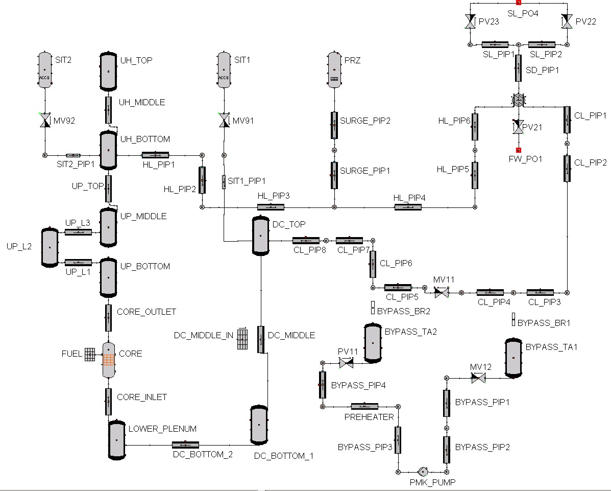
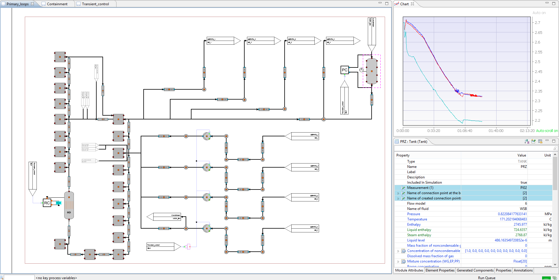
APROS (Advanced PROcess Simulator, http://www.apros.fi) has been used at the Institute of Nuclear Techniques for education and research since 2000. This system code is being developed by the Finnish Fortum company and the VTT Research Institute for the analysis of nuclear power plant incidents and accidents (e.g. loss of coolant accident). APROS is suitable for two-phase, coupled thermal-hydraulics and reactor physics calculations in a one-dimensional approximation. Students learn to use it through laboratory exercises, and those who are more interested can use it for complex modelling tasks for BSc/MSc thesis work.
Wide range of research topics are available: simulation of benchmark problems for test facilities, investigation of power plant transients, development of new mathematical-physical models for APROS using Fortran, C or SCL language.
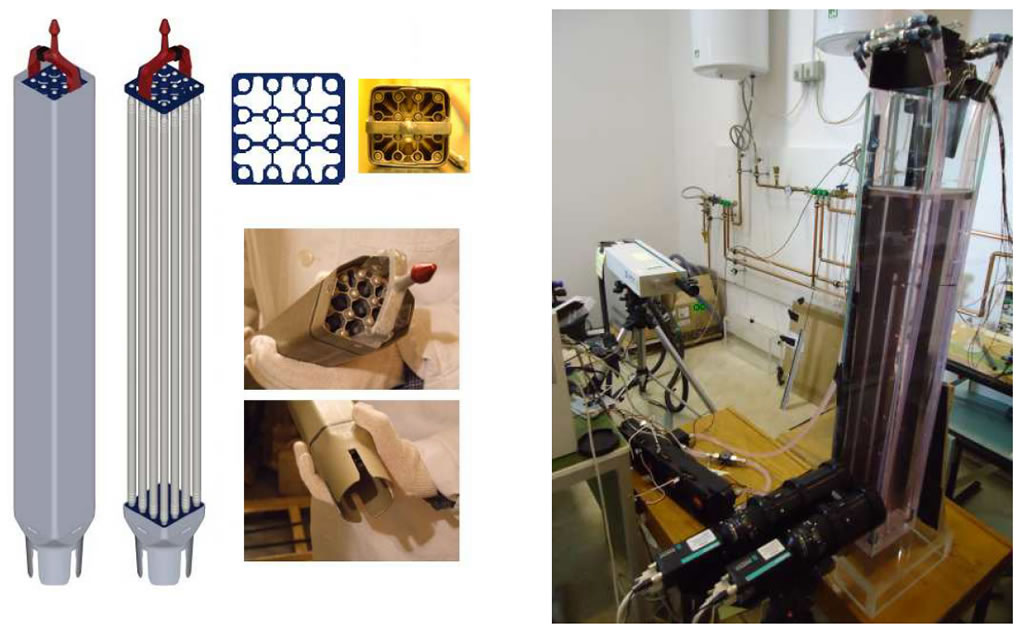
Particle Image velocimetry in nuclear research
Concept of Particle Image Velocimetry (PIV)
PIV is a state-of-the-art flow measurement method based on the recording of particle images. Flow-following particles are added to the liquid that will move together with the the same speed as the fluid. Flow velocity can be determined from the velocity of the particles. In general flow-following particles have a density close to the density of the liquid. In practice with water as working fluid usually polyamide or polystyrene particles of 5-50 micron diameter are used.
Velocity of the flow-following particles is determined using the following optical method. A high-powered light source (generally a pulsed or continuous laser) illuminates the particles for a short period of time and a digital device (camera) records the light scattered on the particles, thus recording the location distribution of these particles. In case of pulsed lasers the light source acts similarly to the flash of a camera, while with continuous mode lasers the shutter of the image recording device will start and end the exposition. Recording two subsequent images with a short time delay displacement of the particles can be recorded. By knowing the time delay and the displacement, with the help of correlation methods the instantaneous velocity field can be derived for the recorded area.
![General arrangement of a PIV measurement [M. Raffel, C. Willert, S. Wereley, J. Kompenhans: Particle Image Velocimetry - A practical guide, Springer, Berlin, Germany, 2007]](/images/article/kutatas-fejlesztes/termohidraulika/PIV_elv.png)
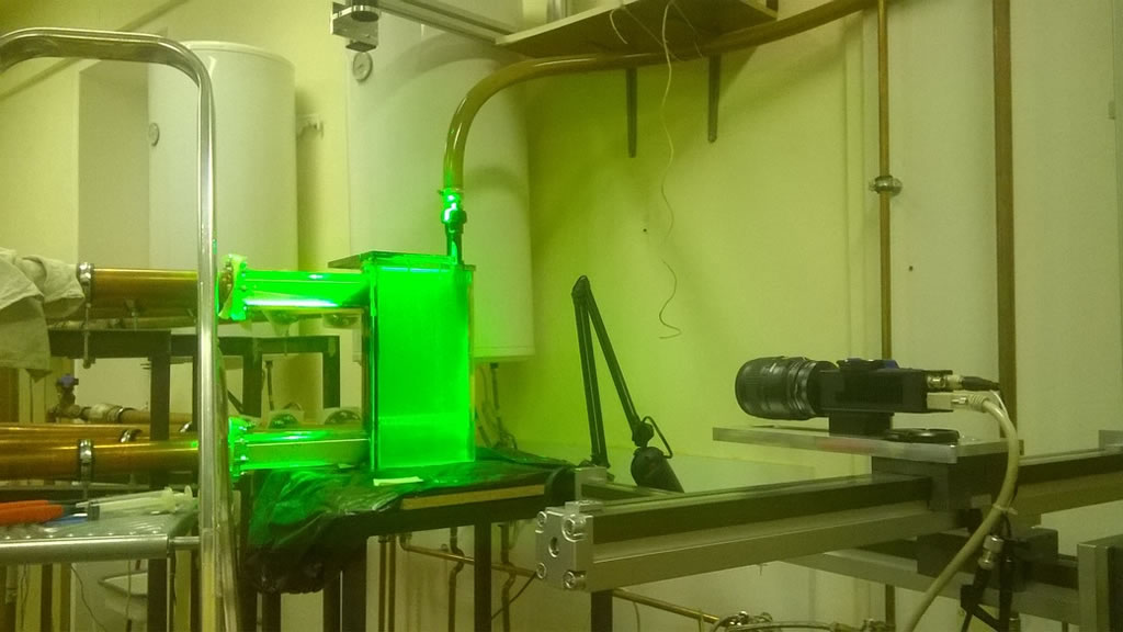
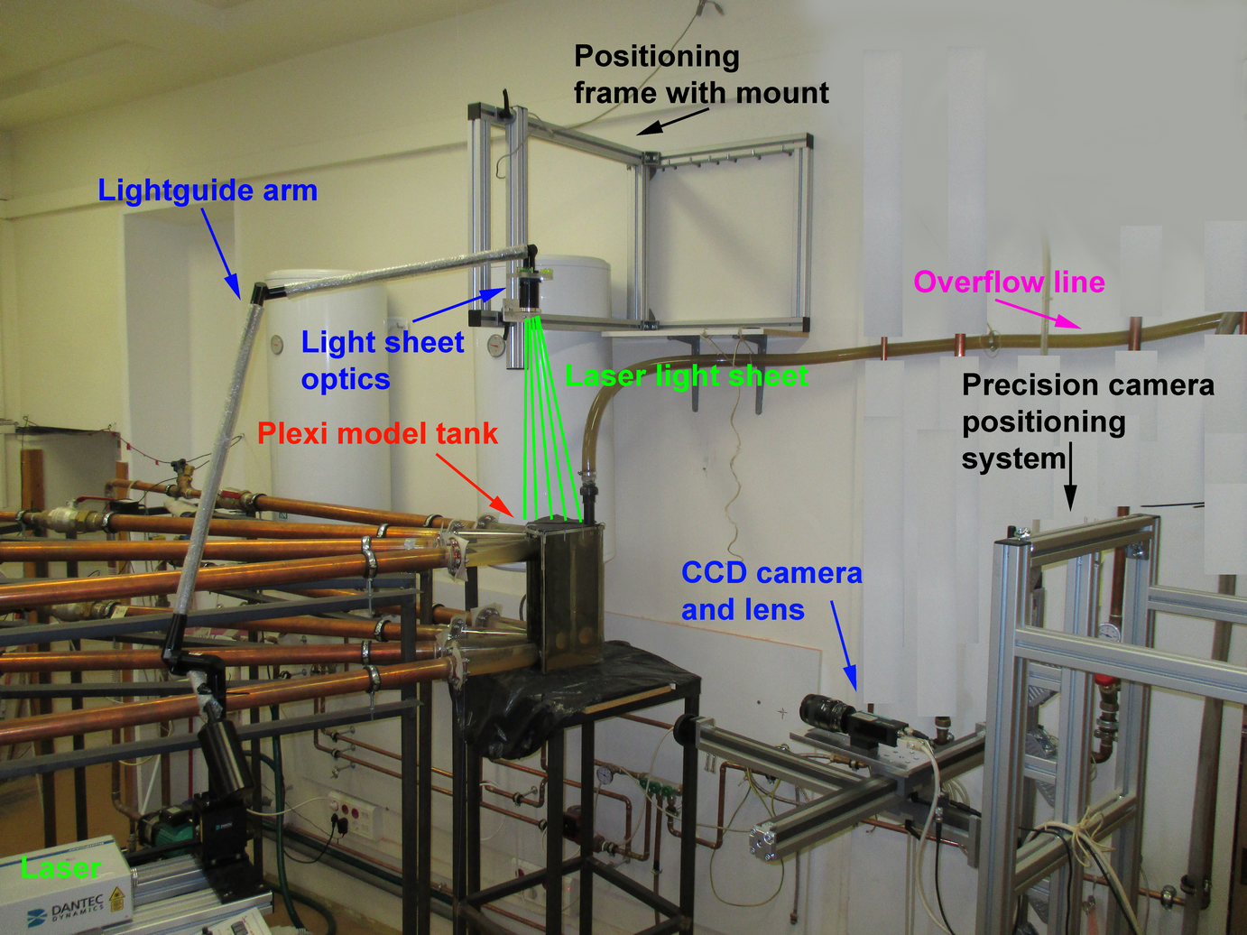
General arrangement of a PIV measurement is shown above. For high-speed pulsed light sources dual head laser are used generally. The two heads – practically two lasers – allow the generation of very short pulses with very short time delay between them. In case of a dual laser the beams coming out from each one are combined together using optical elements (mirror, polarisers, lenses) and directed into the measurement volume using a light guide arm. With the help of lenses the cylindrical beam is shaped in order to get a light sheet. The light sheet is supposed to be positioned according to the flow direction, and the image recording camera – under ideal circumstances – should be positioned perpendicular to the light sheet.
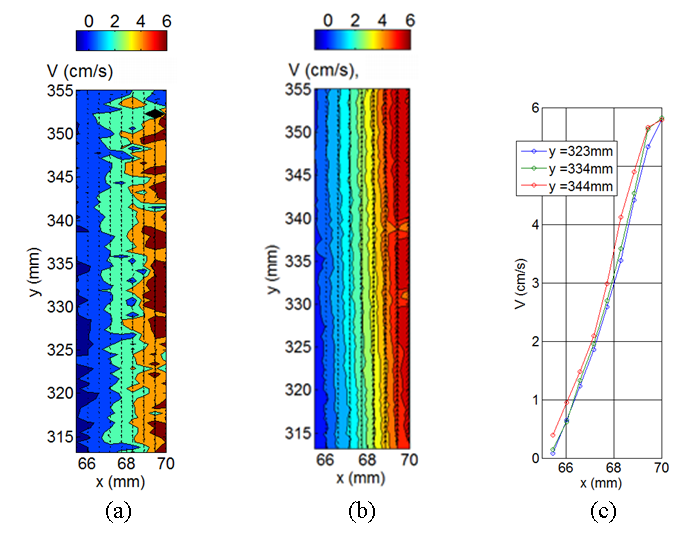
With the application of PIV fundamental flow phenomena can be investigated in complex geometries without disturbing the flow (for example by inserting probes). The measurement data can also be used for validation of numerical models and calculation results.
PIV measurements in training and education, research